LINKS:
X10 Receiver Project
I have created a kludge to operate the projection screen in our church auditorium. This mess consists of two X10 Universal modules that operate an Up and a Down solid-state relay, with some intervening logic to prevent the Up and Down relays from being turned on at the same time. However, it's big, klunky (noisy), custom-built, and perhaps the under-spec relays are responsible for burning out the motor once some time back.
A better solution is a clean project that puts the X10 receiver and relay steering logic inside a microcontroller that operates two LARGE solid-state relays. Smaller package, quiet, reliable.
Microchip has already designed a PIC-based X10 receiver, and publicly documented it in their AN236 app note. It includes theory of operation and a schematic diagram. However, it is kind of an experimenter's board, and includes a real-time clock and A/D converters which are not needed for this project, so I replaced their PIC16F877 with a smaller, cheaper PIC16F87.
Because this project does not operate an liquid-crystal display (LCD), it doesn't need as much power, so using Microchip's TB008 tech brief, I selected new values for the transformerless power supply.
Additionally, since the 16F87 has a built-in UART serial port, and I'm an experimenter, I designed in an RS232 converter, which can be left out of "production" cards.
The parts were ordered from Digikey, and the circuit boards were ordered from BareBonesPCB, a service of Advanced Circuits (who also offer a free Design For Manufacturing (DFM) service). The artwork was laid out two-boards-per-panel, which is supposedly as large as the free version of Eagle will let you produce. I also got an isolation transformer - you don't want to mess with a transformerless power supply plugged directly into the mains. I suspect you also don't want to connect a computer via the PIC programmer to the isolated project board unless the computer is also isolated.
Sept 21 2006:
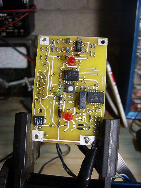
Slow going, too many distractions. I've assembled the power supply, the microcontroller, the switch, and the LEDs, and verified that I can download and execute programs. I've also mounted the Maxim RS232 converter, but have not successfully communicated with the project.
Oct 10 2006:
The RS232 is now working fine. I've written a "monitor" with memory peek/poke capability. The X10 Receive parts are now on the board, but of course, it doesn't work. I have to troubleshoot. Unfortunately, my Tek 541 is down (for a long time), and I don't know if my antique DuMont oscilloscope is up to the job. Long past time to upgrade my test equipment...
Nov 21 2006:
All done.
Turns out the old DuMont worked fine (or as fine as a 1950s era scope can work).
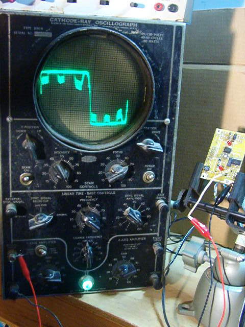
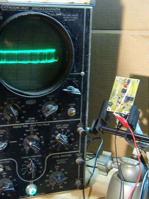
To the left, the input to the X10 circuit, at the collector of Q1 (with Q1 and the 50ohm not yet installed), with a Maxi Controller issuing a command. The 120KHz bursts at three-phase zero-crossings are clearly visible. To the right, the output of the last inverter; shows pulse activity, so the 120KHz bursts are indeed being detected and converted to logic levels. Nothing to stop the micro from working.
So pulses are being detected, but the software doesn't detect them... Turns out, the software only looks right at the zero-crossing. But with the latency through the filters, the detection pulse cannot be present until some time after the zero-crossing! I rigged up Timer 1 to measure the time from the zero-crossing interrupt to the "true" at the detect input: about 110 microseconds - a long time for a PIC! So I changed the logic to capture the occurrence of a 120KHz burst any time during the half-cycle, and X10 reception started working flawlessly!
I then installed the rest of the circuit, for X10 transmit. After a bit of flopping about, I found my code error and X10 Transmit began working fine. I added and tested the rest of the functional code (now available below), and now I was ready for the final tests.
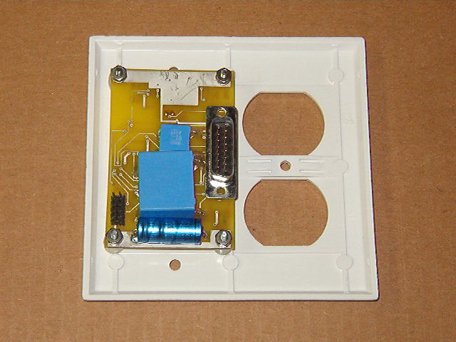
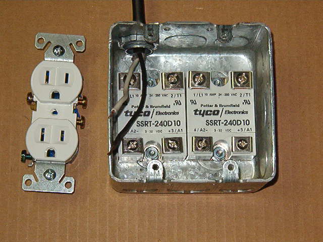
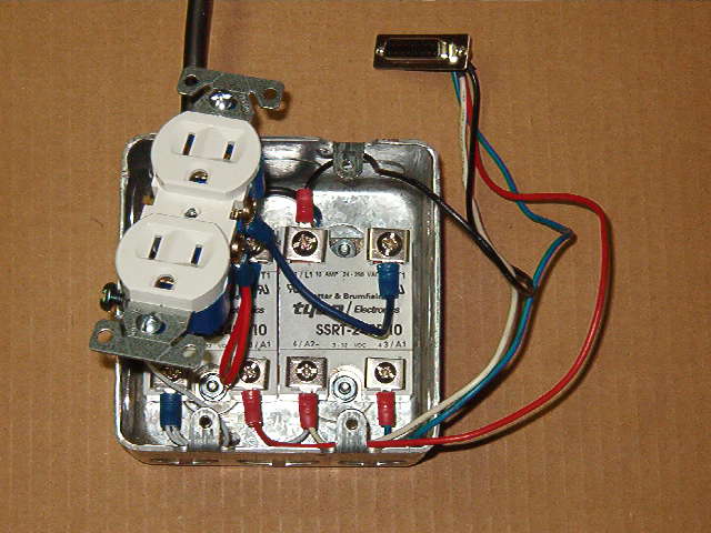
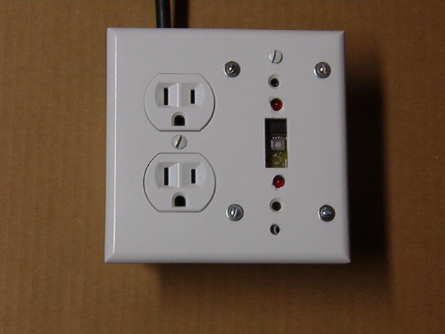
Top Left: Circuit board mounted to a two-gang duplex-and-switch wallplate. Note the large X2-rated line capacitors. Top Right: The box contains the two large 10-amp relays. I think these will stand up to light motor tasks, don't you? Lower Left: Wiring attached. Lower Right: Finished unit. The ugly wallplate was in my junkbox; for the Real Thing, I will get a duplex-and-blank wallplate, and more properly insulate the mounting screws.
Test Results: With the Maxi Controller or a standard Mini Controller (lower voltage output) plugged into the isolation transformer along with the Box, it works fine. It seems X10 won't go through an isolation transformer (no real surprise), so I then put them on an extension cord into the wall. Same results. However, when I try the controller in the outlet across the room, it won't work reliably if a "filtering" extension strip is plugged into the same outlet as the box. Hmm... So I take it to church. Sure enough, even though there is a Leviton X10 phase coupler/amplifier in the building, it won't pick up command signals from the control console in the back, but it will (unreliably) pick up signals from another outlet nearby at the front of the auditorium.
Conclusions: Not acceptable. Not nearly sensitive enough. I believe the problem is the reference design's use of a CD4069 CMOS hex inverter as an amplifier. This is a common trick, but I cannot believe that a logic inverter can have as much gain as an op-amp designed for the purpose. So the next step in this project is to replace the hex inverter with an op-amp filter circuit.
Dec 26 2006:
I'm putting this project on hold for a bit. I'm shifting to the use of gSchem and PCB, free/open-source circuit board design tools that may not be as polished as Eagle, but don't have the size restriction or the high price tag. I intend to create a "daughter board" to put an op-amp in place of the hex inverter. I've also got some of that Tec Blue iron-on resist material, so we will see how that goes. Just got to climb the learning curve (and find time for that). Stay tuned...
RESOURCES:
- Eagle Project (with CD4069 hex inverter; obsolete. 700K)
- Parts list
- Source Code