Sega Genesis Controller
Hack for TI-99/4A
The TI-99/4A allows joysticks to be attached for games; however, the TI joysticks are wierd things, two joysticks on a single "wye" cable, and the joysticks are not particularly well-made. Via an adapter, normal Atari 2600-style joysticks can be connected. At this point, it is hard to find normal Atari 2600-style joysticks, but there are thousands of controllers that are similar. For instance, the Sega Genesis controller is largely compatible with the Atari.
The problem is, the Sega controller relies on 5V from the console to operate its internal active electronics, and the TI doesn't provide any. The joysticks are just an extension of the scanned matrix keyboard. So to modify any alien controller, the internal electronics must be disabled, and it will no longer be useful in its original context.
The Simple Hack
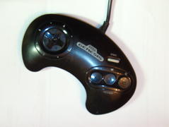
With that in mind, here's the simple hack to make the Sega Genesis 3-button controller "the same as" a classic Atari 2600 joystick.
It already has a 9-pin "D" style connector.
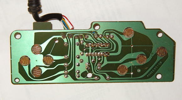
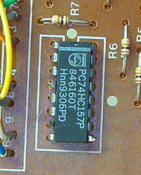
When you open it up, there's a single logic chip inside, and the traces from the switch contacts. When I followed the circuit board traces, I found that the left/right switches already go to the correct pins on the connector, and the up/down and "B" fire button switches almost do.
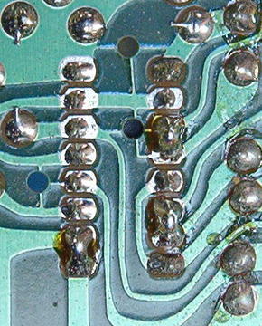
The hack is: Cut pins 4, 7, and 9 on the logic chip, and glob solder to form bridges between pins 3 and 4, between 6 and 7, and between 9 and 10. Remember that Pin 1 is on the top left of the package, when the "notch" on the package is at the top, and the pin numbers advance down the side and up the opposite side. When the board is flipped over, this is reversed, of course.
That's it! Reassemble, plug it into the TI via an Atari-to-TI joystick adapter, and enjoy your Parsec game!
Note that with this mod, only the "B" fire button works. The "A" and "C" buttons do not have traces that go to the right pin on the 9-pin "D" connector. Of course, this doesn't prevent you from using wire jumpers to put all three switches in parallel, but that goes beyond the "simple hack" state, and really, how many fire buttons do you need?
Now, I've modified several controllers in this way, and most were of the style described above. One, however, was apparently of later manufacture, and had a surface-mount logic chip and graphite switch contacts rather than gold-plated ones. The same hack applies, but I found it easier to desolder and remove the logic chip than try to cut leads; the finer lead pitch on surface mount devices simply doesn't admit the jaws of wire cutters.
The More Involved Hack
I had used controllers modified like this for many years, until I noticed that it was getting harder and harder to get the switch contacts to "make". Some controllers ceased to work at all. I believe the problem is that the switches are bare contacts on the circuit board, and a conductive "slug" embedded in the rubber jacket that sits over the contacts has to "make" the connection. I believe that over time, the "slug" looses its conductive virtue. The solution is to replace the cheapo switch with a real switch.
That time has come. I borrowed a micrometer from a friend at work, and measured the height of the rubber jacket for both switches and joypad. The switch jacket is 0.195 inches high (0.150 inches when depressed), and the joypad jacket is 0.145 inches high (0.100 inches when depressed). What we want is a surface-mount switch with a button that extends well above the switch body, for which the overall height is as close to the joypad height as possible.
The Panasonic EVQ-PHP03T fits the bill, as available from Jameco as SKU 2076236. It has the additional advantage of being maybe 30 cents each. So I got several.
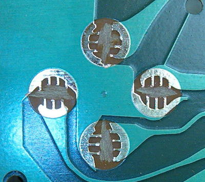 The first thing I did was to use a Dremel tool to grind away the intermeshing contact "fingers" on the circuit board. In retrospect, this probably wasn't necessary, as the Panasonic switch has no metal underneath it, but I think it is still safer - once the switch is mounted, there's no seeing underneath it, and it's tough to get it off. Better safe than sorry.
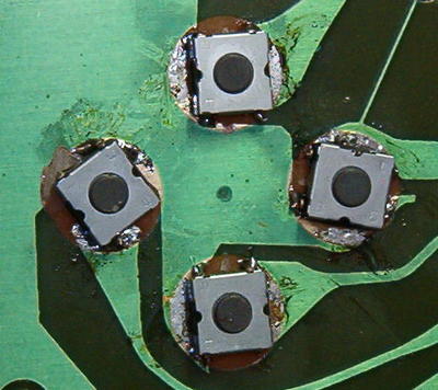 Next is mounting the switches. Note there are four solder tabs on the switch. Tabs on opposite sides but at the same end are connected together internally. Soldering both tabs down would be best for mechanical rigidity, but only one on each end is required for electrical contact. In most cases, both contacts on the same end can be soldered to the same half of the switch pad. Note the contact on the left in the above picture; the "bottom" contact is quite narrow relative to the "top" one. It was possible to get only one of the contacts on this narrow pad, and part of the "top" pad had to be ground away with the Dremel tool to avoid bridging with the opposite solder tab. This is why this switch is "diagonal", where the others line up more squarely.
Locate the switch so the button is about right in the middle of the circular switch contact area, and so the switch solder tabs sit on their respective pads. Note where one tab is, and using the surface-mount soldering iron, tin that area of the pad. Then tack-solder the switch contact to the tinned area after repositioning the switch. This will anchor the switch while the other tabs are being soldered down.
After each switch is soldered, use an ohmmeter to verify that the contact is open unless the switch button is pressed. Note that only five switches are required - four for the joypad, and one for the "B" fire button (unless you have also ganged the "A" and "C" buttons to the "B" circuit trace). Remove and discard the rubber jackets from the joypad, the "B" button, and any other switches you have replaced. Reassemble the controller, and enjoy your Parsec game with crisp tactile snaps from the new switches.
Now, the minority controller with the graphite switch contacts can be modified the same way. Using a knife or a small screwdriver, scrape the graphite from the circular pad at each end of the switch contact, revealing the copper pad underneath. Opposing solder tabs of the surface-mount switch will just make it to these pads. Tin both pads prior to soldering, as the graphite makes it difficult to solder to the copper, and it may take a bit of solder for the enclosed flux to clean away the graphite. Then tack down opposing solder tabs and doctor the solder joints. There are only two contacts holding the switch to the board, but that should be adequate.