Evaporative Cooler Controller Project
My backyard workshop/storage shed is one of the nicer features of my property. However, there's no environmental control; in the winter, it gets too cold to work out there, and in the summer, it gets too furiously hot to work out there. In the winter, I can set a space heater near my bench, and it's tolerable. In the summer, the best I can do is hang a fan from the roof trusses, and it blows the hot air around. It helps me (marginally), but it isn't doing a thing for items, especially old computers and magnetic media, to be soaking in 100-degree-plus heat.
As of May 2021, the evap cooler on the house had reached its end-of-life, I had it replaced, and at the same time, got the HVAC company to install an evap on the workshop. The way I wanted it, with the cooler in the back where it can't be seen or heard, and some ductwork running up under the eavees and in between the trusses and some downdraft diverters mid-building.
And I placed the wiring for it. Conduit to a box outside; two boxes, actually, the control outlets for the cooler and some utility outlets for garden equipment (to fight the encroachment of bermuda-grass and tumble-weeds and palo-verde trees). A branch for a box in the ceiling over my computer carts for a pendant outlet. And a box to house the Mark II evap cooler controller.
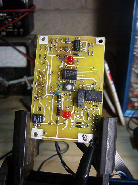
Similar to the Mark I still in service in the house - a PIC microcontroller monitors 60Hz line frequency for time-keeping and the furnace contacts of the thermostat. When the temperature exceeds the set-point (and the thermostat contacts open), turn on the pump for 30 seconds to moisten the pads, and then turn on the turbine. When the temperature drops below the set-point, turn off the pump and let the turbine dry the pads a little and then turn off 30 seconds later. This controller is circa 95% junkbox - I bought the box, some fuses, a TO-92 5V regulator, a TO-92 adjustable regulator (to supply 3V to the thermostat so I don't have to use penlight batteries anymore), a terminal block, and a four-wire wiring harness. Everything else is out of my "lab stock" and/or reused/recycled junk I've had for a while.
I was torn between doing the controller board as perf-board and hand-wired point-to-point connections or doing a printed circuit board. It's a very simple circuit, very amenable to perf-board work. However, I chose to brush up on gEDA and PCB (geda-project.org) and try out the budget printed circuit board service provided by Digi-Key, what they call DK Red. $1.50 per square inch, between 1"x1" and 10"x10", two-sided - this will work for me. Turned out pretty good.

Software was easy, a simple state machine. I didn't bother with going to sleep, since it's running off the mains. At first, I used a solid-state relay rated for 10A to run the turbine, but after I built the box and it was running for a while, I happened to touch the plastic box in contact with the relay - flaming hot. Apparently SSRs dissipate when they're on. This won't work. Sometimes, the old ways are better. I had a "ice-cube" relay with 10A contacts in the junk box, with a 120VAC coil. I had a small PCB relay with 120VAC rated contacts with a 5V coil. In the end, I made a little perf-board assembly with a FET and the smaller relay to drive the larger relay; this way the logic-level drive signal from the board (I contemplated doing a board respin to add the FET and small relay but decided to not bother). It's a bit clumsy, but it's all junkbox and the only power dissipated is the relay coil - very minor.


The solid-state relay that was getting too hot had the nice attribute of switching on the zero-crossing; that is, after the control voltage was asserted (or deasserted), the relay doesn't actually take action until the voltage at the terminals (which is the AC "Hot" line on one side and the AC "Neutral" line fed through the external equipment, in this case the motor, on the other" are within some small tolerance. This prevents large transients. Now that the system doesn't use a SSR, this feature is not "built in", and it's potentially even more important to prevent arcing across the relay contacts, especially when opening (the "break" arc is more powerful than the "make" arc). I could have included an arc suppression circuit, but I don't really have a good place to put it. So I attempted to do it in software.
The object was the measure the time from the relay contacts opening to the next zero crossing. Since the micro operates the state machine at the point of detecting the zero crossing, via the opto-coupler, it has 1/60 or 16.7 milliseconds to the next zero crossing. Assuming both relays transition in the usual 5 to 8 milliseconds, delaying the turbine signal by around 3 to 6 milliseconds should move the relay transition to near the next zero crossing. This measurement really can't be done except for a single-capture storage oscilloscope. After fighting with an inexpensive (rescued from some past TOW lab cabinet clean-out), three things were discovered:
- The opto doesn't switch at the zero crossing. The rising edge of the opto output happens when the internal LED turns off. With the simple resistor drive, the LED turns off when the AC mains voltage drops below a certain point. So it's actually just before the zero-crossing. But at least it happens reliably.
- The relay operating time is quite variable. This is aggravated by having two relays in the path. It may also be aggravated by the way an AC coil relay works.
- The cheapo USB instrument and the software are barely usable. In single-shot mode, one or the other channels is sampled, but not both. A measurement depends on the relation between the trigger signal (the relay control output) and the monitored AC mains voltage being consistent. For the technique I was using, this was mostly true. It was still very frustrating. I need a decent digital storage oscilloscope, or at least a higher-end USB gadget.
In the end, I decided that, without a feedback signal by which to calibrate the delay dynamically, a "canned" delay would not adequately synchronize the highly variable relay action time with the AC zero crossing. So, no arc suppression. As infrequently as the controller is expected to operate (a few times a day - or once a day during the monsoons; it turns on in the morning and stays on until after midnight), I'll just live with the wear on the relay contacts.
RESOURCES:
- Project Files - gschem schematic files, PCB file, symbols and footprints, MPLAB X project structure
- Controller subsection schematic
- Power subsection schematic